Ⅰ. Introduction
Structures are born into this land with the destiny to fulfill their roles by transferring numerous loads imposed on them to a sturdy foundation. Therefore, structures installed on less robust soils, often referred to as poor foundation soils compared to solid rock foundations, demand unnecessary piles from designers in order to fulfill their mission to those born with a golden spoon.
When asked about what is crucial in the analysis of structures, I would answer with quantification of loads, abnormal behaviors of structures, and boundary conditions. Among these, the aspect where an engineer's judgment plays the most significant role is the "boundary conditions." It is emphasized that the accuracy of modeling the behavior of actual structures depends on how closely it can replicate real conditions, and this is intricately tied to boundary conditions.
To design a pile foundation on poor soils, currently practiced methods in the field can be summarized into four as follows.
Method 1:
Interpreting the foundation top as a fixed support, calculating pile reactions and displacements using the elastic analysis method (displacement method).
Method 2:
Modeling the pile up to a virtual fixed point (1/β).
Method 3:
Full Modeling method, including the entire pile (ground springs distributed based on pile nodes).
Method 4:
Modeling the stiffness of the pile foundation with a 6-degree-of-freedom spring at the foundation top node.
Among these, 'Method 3' is judged to most closely simulate the behavior of actual structures. However, when conducting full modeling of the structure, including the pile, it is necessary to consider springs at each pile node based on the ground conditions as boundary conditions. This makes the modeling heavier and significantly increases the analysis time. Therefore, in practical applications, methods 1, 2, and 4 are often applied for design to reduce computational complexity and analysis time.
In this content, I will illustrate one example of design using 'Method 4' and then explain common errors made by designers based on structural mechanics knowledge. Subsequently, I will describe how to apply this knowledge in practice.
Ⅱ. Design Case and Errors
2.1 Structures Requiring Method 4 Design
One of the representative structures that require the design approach of 'Method 4' is the foundation of wind turbines. To understand the reasons behind this, it is essential to comprehend the structure of wind power projects.
In onshore wind power projects, the cost of purchasing wind turbine components accounts for a significant portion, roughly 60%, of the total development project cost (including land, turbine foundations, transmission lines, control buildings, substations, etc.).
Wind turbines must obtain certification from the International Electrotechnical Commission (IEC) regarding their performance. Safety considerations for the tower are also included in the evaluation criteria. In other words, the structural safety of the tower is a guarantee that the wind turbine manufacturer must provide. Consequently, the role of structural engineers is quite limited when it comes to wind power projects.
This raises a question: how do wind turbine manufacturers establish boundary conditions when conducting structural reviews of the tower? One of the three crucial aspects mentioned in the introduction was boundary conditions. Do wind turbine manufacturers know the soil conditions under the foundation, which is necessary for ensuring safety?
The answer to this question lies in the rationale for applying 'Method 4' in the design.
Wind turbine manufacturers use programs like GH-Bladed to simulate and validate wind turbine systems, taking into account factors such as wind speed, turbulence, aerodynamic asymmetry, and other relevant parameters. They establish wind turbine test sites to receive certification for wind turbines, including safety considerations for the tower.
To ensure the stability of the system, wind turbine manufacturers provide the conditions for the foundation design, incorporating the aerodynamic characteristics of their wind turbines. This information is shared with the companies responsible for Engineering, Procurement, and Construction (EPC) during the wind project development process, enabling them to utilize it in the foundation design phase.

The following are the Preliminary Requirements for the foundation that two wind turbine manufacturers, involved in a wind project I participated in, provided:
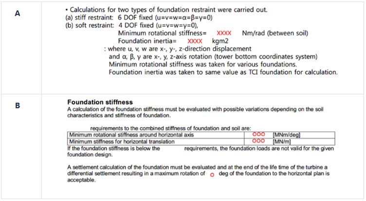
In essence, it is necessary to assess whether the characteristics of the wind turbine foundation can be defined by a 6-degree-of-freedom at a single node to meet the manufacturer's requirements. Therefore, the design approach of 'Method 4,' as mentioned in the introduction, is needed.
To briefly summarize the wind turbine foundation design process:
The wind turbine manufacturer assumes the conditions under which their requirements are satisfied and provides the sectional forces acting on the bottom of the wind turbine to the EPC company (or design firm).
The EPC company calculates the size of a safe and stable foundation based on the given loads and conveys the foundation's stiffness to the manufacturer.
The wind turbine manufacturer recalculates the loads considering the foundation's stiffness and finalizes the imposed loads, then communicates them back to the EPC company.
This iterative feedback process continues for several cycles. Therefore, the EPC performing company must accurately calculate the stiffness of the foundation they are designing and communicate it appropriately to the wind turbine manufacturer.
2.2 Practical Application in Design
During the initial project execution, despite being a civil structural engineer, I found myself in an unusual position overseeing EPC contracts and equipment procurement. It would have been preferable to outsource even the civil structural design, but due to the insistence of a senior executive committed to cost-cutting, the responsibility for design inevitably fell directly on my shoulders.
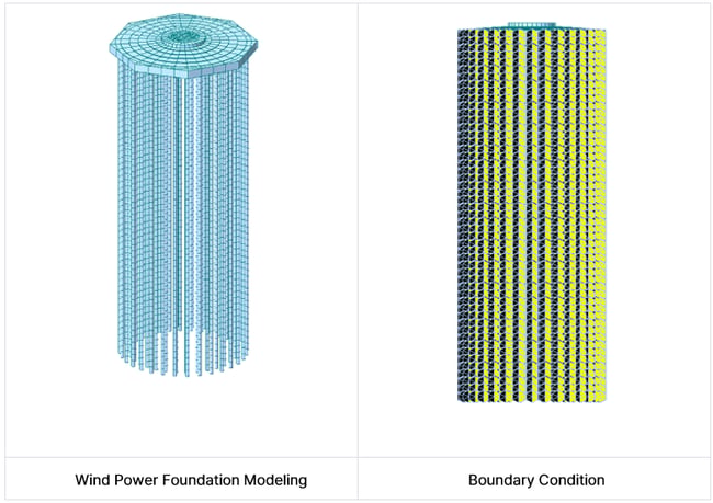
The following figure illustrates the modeled configuration and boundary conditions of the foundation used in this project.
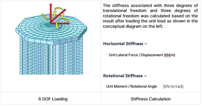
While progressing with the design, contemplating how to calculate the foundation stiffness considering the ground conditions at the location where the wind turbines are installed, I opted for a method commonly considered by engineers.
And based on the results incorporating the calculated foundation stiffness, the wind power generation site, constructed using structural calculations that account for the sectional forces at the tower base, is currently completed and in operation, producing commercial power. However, I realized belatedly that there was a significant error in this review.
#Foundation stiffness
#Pile foundation design
#Boundary conditions
/%ED%86%A0%EB%AA%A9%EB%A7%8C20%EB%85%84_400_400.png)
A civil structure engineer & architectural structure engineer who loves structures.
※ Click on the keywords below 'Topics' to view related content.

![Design and Practical Examples of Baseplates and Anchor Rods [sample download]](https://2495902.fs1.hubspotusercontent-na1.net/hubfs/2495902/%EC%8D%B8%EB%84%A4%EC%9D%BC22.png)
![Understanding Drafting Standards [ Drawing download ]](https://2495902.fs1.hubspotusercontent-na1.net/hubfs/2495902/%EC%8D%B8%EB%84%A4%EC%9D%BC24.png)
![Key Changes in ACI 318-19: A New Standard for Structural Design [ PDF download]](https://2495902.fs1.hubspotusercontent-na1.net/hubfs/2495902/%EC%8D%B8%EB%84%A4%EC%9D%BC21-1.png)
![Design and Practical Examples of Lug design(ASME BTH-1) [sample download]](https://2495902.fs1.hubspotusercontent-na1.net/hubfs/2495902/%EC%8D%B8%EB%84%A4%EC%9D%BC20-1.png)

%20PSC%20%EA%B3%84%EC%97%B4%20%EA%B1%B0%EB%8D%94%EC%9D%98%20%ED%9A%A1%EB%A7%8C%EA%B3%A1%20%ED%98%84%EC%83%81%20%EB%B0%8F%20%EC%B2%98%EB%A6%AC%EB%B0%A9%EC%95%88/Author_%ED%86%A0%EB%AA%A9%EB%A7%8C20%EB%85%84.png)