Finite Element Analysis and its application to Geotechnical problems
The usual dilemma in soil as an engineering material is its inconsistent parameters. That is why the Finite Element Method application in geotechnical problems has been a requirement for almost all soil-related projects. Its development through the years, together with the advancement of computing packages, has evolved this option from a research tool into a daily engineering tool.
FEA results, although colorful and eye-catching, also have significant drawbacks. Limiting these to a minimum is subjective yet controllable. Here are 3 things that you should consider prior to hopping into Finite Element-based Geotechnical Analysis.
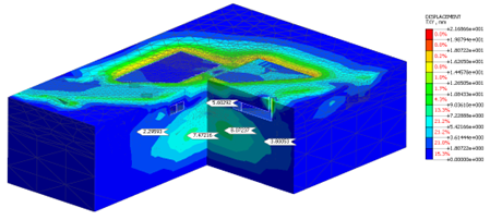 Figure 2: Visual results of stresses in an FE model
1. MODEL SIMPLIFICATIONS
The idea of using computing packages to simulate a real-life phenomenon still requires a sound theoretical understanding of its underlying mechanics. Since a computer model is used to represent a reality, the conceptual model of it must be validated and verified by mathematical and numerical models. These verification models incorporate the mathematical formulation of the process in your conceptual model (differential equations describing equilibrium in a continuum model, stress-strain relationship describing the soil deformation behavior, etc.).
The implementation of the numerical schemes in the software is incorporated by the developers who made prior series of mathematical verifications.
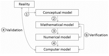 Figure 3: Simplified Modeling process from Reality to Computer Model
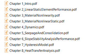 Figure 4: Sample Verification files compiled by developers of a computing package
*Verification files of GTS NX is compiled in the installation files (see: “Benchmarks&Verification” folder. C:\Program Files\midas\GTS NX\Manual\Benchmarks&Verification)
Depending on the package used, model simplification comes in a lot of ways.
● Geometrical simplification
● Limit and boundaries assignment
● Definite Material behavior
● Simplifications in the construction process
2. MESH SIZING
In Finite Element analysis, the larger number of elements present in the model, the longer the analysis will converge. However, there are ways to optimize the package and reduce stress analysis time, apart from troubleshooting the possible hardware and software issues.
One approach is by targeting an area to apply finer mesh relative to the whole model. In areas where steep stress gradients and plastic strain localization is expected, a finer mesh size must be used. Therefore, initial models may be done as conventional beam models then refine the model in FEM.
You can check more of these details in the download file.
3. LIMITATIONS OF ELASTICITY
CONCLUSION
REFERENCES:
“Validation of Geotechnical Finite Element Analysis”
Brinkgreve R.B.J.
Delft University of Technology & Plaxis bv, Delft, The Netherlands
“Finite element analysis in Geotechnical Engineering”
David M. Potts and Lidija Zdravkovic
Imperial College of Science, Technology and Medicine
“Introduction to FE based Geotechnical Analysis in Midas GTS.”
Advanced Geotechnical and Tunnel Analysis Systems

Engineer. Mark Joseph Carino is a registered civil engineer with over 5 years of experience in various engineering fields mainly in structural design of flood control structures, bridges and geotechnical engineering.
※ Click on the keywords below 'Topics' to view related content.


![Design and Practical Examples of Baseplates and Anchor Rods [sample download]](https://2495902.fs1.hubspotusercontent-na1.net/hubfs/2495902/%EC%8D%B8%EB%84%A4%EC%9D%BC22.png)
![Understanding Drafting Standards [ Drawing download ]](https://2495902.fs1.hubspotusercontent-na1.net/hubfs/2495902/%EC%8D%B8%EB%84%A4%EC%9D%BC24.png)
![Key Changes in ACI 318-19: A New Standard for Structural Design [ PDF download]](https://2495902.fs1.hubspotusercontent-na1.net/hubfs/2495902/%EC%8D%B8%EB%84%A4%EC%9D%BC21-1.png)
![Design and Practical Examples of Lug design(ASME BTH-1) [sample download]](https://2495902.fs1.hubspotusercontent-na1.net/hubfs/2495902/%EC%8D%B8%EB%84%A4%EC%9D%BC20-1.png)


