1. Introduction
On Sunday, August 1, 1976, at around 4:40 a.m., Reichsbrücke, which was crossing the Donau River, collapses in Vienna, the capital of Austria. Fortunately, there was little traffic because it was early in the morning, but unfortunately, a young man lost his life. Although there were few casualties, the collapse of a bridge in the heart of Austria's capital caused a major issue. A few months later, the collapse investigation committee blamed the destruction of concrete in the bridge's support. Cracks grew in the plain concrete, which eventually led to the collapse, due to the cracks caused by the contraction and expansion of the penetrated moisture, as well as the unexpected flow of force in the area where the concentrated load was acting, and the absence of steel bars that could receive the tensile force [1].

.png?width=751&height=237&name=%EA%B7%B8%EB%A6%BC%202%20%E2%80%93%20%EC%97%AD%ED%95%99%EC%A0%81%20%EC%8B%9C%EC%8A%A4%ED%85%9C%20(Statical%20system).png) Fig 2 – Statical system
Fig 2 – Statical system
If we could understand the flow of force due to the concentrated load on concrete at the level we are today, we might still see the Reich bridge crossing the Donau River.
Understanding the Strut-Tie-Modell (STM), a key topic in this article, will allow you to not only see the flow of force, but also easily guess the form of reinforcement required for the structure.
2. Main Subject
2.1 B region and D region
When we design structures, we use the Euler-Bernouli beam theory, whether we know it or not. The core of this theory is the assumption that when a member is subjected to bending, the cross section perpendicular to the neutral axis remains flat after deformation. In reality, measuring the strain of a slab shows a nonlinear distribution, but since it is not large, even the assumption of plane maintenance of a section can predict actual behavior with sufficient reliability. It would be nice if all the structures were designed in multi-engineered beam theory, but in reality, they are often faced with insufficient design of this theory because it is much more complex and there are many exceptions. Areas like this are subject to concentrated loads or where the cross section of a member varies greatly and shear deformation cannot be ignored, and these are called irregular regions, D-regions. This is to be remembered by distinguishing it from the beam-region or B-region to which the Euler-Bernoulli beam theory can be applied. The STM introduced in this article is one way to design D-regions to which beam theory does not apply.
2.2 STM Components
STM is the idealization of the behavior of reinforced concrete members in truss form. It is very difficult to grasp the actual stress distribution of the members with our intuition, but considering the characteristics of reinforced concrete, the flow of force is simplified and expressed like truss. This will not only predict the behavior of the members, but also design them.
STM consists of three components. Compression materials subjected to compressive force, tensile materials subjected to tensile force, and nodes at which the tensile material meets the compressive material are called STM. The truss model consisting of a strut, a tensile material, and a node in reinforced concrete is called STM.
.png?width=674&height=573&name=%EA%B7%B8%EB%A6%BC%203%20%E2%80%93%20%EC%8A%A4%ED%8A%B8%EB%9F%BF-%ED%83%80%EC%9D%B4%20%EB%AA%A8%EB%8D%B8(STM).png) Fig 3 – Strut-tie Model(STM)
Fig 3 – Strut-tie Model(STM)
2.3 Three(3) fundamental principles
There is one thing to remember when designing an assembly using STM. This is not a way to find a single correct answer with very high accuracy, but a tool to find an approximate value with sufficient accuracy. It is not desirable to try to find a correct answer with more accuracy than necessary by subdividing it to the extent that STM is excessive. It is sufficient to visualize the complex behavior of absence so that the flow of force is visible and find an answer that has the necessary accuracy.
It is often difficult to determine whether the STM you designed is appropriate because there is not one correct answer in this situation, but more than one answer is possible. In this case, I will tell you three of the most basic criteria to look at.
Static equilibrium
The first criterion is static equilibrium. When a rigid body is in a static state that does not move under any force, we say it is in a static equilibrium state. It's a basic concept that we've heard for a long time, but it's not easy to understand. If you think that the sum of the force and moment acting on an object is zero, I think it's enough for STM design.
Let me give you a simple example below.

As you can see above, whether you consider the whole system or cut out a part, you should always meet the condition that the sum of force and moment is zero(0). If the designed STM does not meet the above requirements, you should modify the model to meet this requirement.
Stress-Strain Relation (Material Law)
The second criterion is the stress strain relationship. It defines the relationship between the stress and strain acting on an object when subjected to a force, and you can think of the stress-strain curve of steel bars and concrete that you are familiar with.
 |
 |
|
Fig 5 – Concrete stress-strain curve |
Fig 6 – Rebar Stress-Strain Curve |
The STM design satisfies this condition by ensuring that the forces acting on the compressor (Strut) and the tensile (Tie) do not exceed the compressive strength of the concrete and the yield stress of the reinforcement, respectively.
Compatibility
I think this is the most difficult content to explain in this article. When I first encounter this word, I feel like I'm catching a floating cloud. This is a typical problem arising from translating concepts in English or German into Chinese characters. In order to understand this content more closely, it is better to think about it by reducing the scope. It is about the relationship between strain and displacement, and whether the boundary conditions are appropriate when designing an STM. To understand easily, it is a condition that the behavior of the members and the shape of the truss assumed in the proposed STM should be reviewed. STM design is based on the plasticity theory that presupposes the ductility of reinforced concrete, and if the member is destroyed due to insufficient ductility before moving in the form of the truss proposed by STM, the STM must be modified. Non-linear analysis can be used to prove whether this condition is satisfied, but in this case, the STM design method loses its meaning.
Then, how can we satisfy the conformity condition of our designed STM? To meet this condition effectively, elastic analysis is performed to find out the stress flow without cracks and to design the STM based on this. This will not only allow us to measure the strength of the member conservatively, but also limit the width of the crack to satisfy the usability.
Then, based on the three criteria above, let's look at the two STMs below that have different shapes under the same conditions.

Both models meet the first criterion by satisfying the force equilibrium condition. The compressive and tensile forces are obtained from the truss model defined in this way, and the second criterion is considered so that each member does not exceed compressive and yield stress. Up to this point, the two models are good and bad. However, considering the third criterion, suitability, the evaluation of the two models is different. As can be seen in the figure, the flow of stress in the elastic behavior of the first model and the positions of the compressive and tensile materials are similar. On the other hand, the second model shows that the positions of the compressive and tensile materials are different from the stress distribution. Considering the third criterion, suitability, the first model can be evaluated as "good „ model" and the second model as "bad „ model." In addition, the second model is not a good model because it is difficult to deploy rebar in reality and it is easily expected that it will not satisfy the maximum crack width condition required when using it.
If you consider the three criteria mentioned above when designing, you will be able to design a better STM.
Below, we will look at the relationship between STM and cast reinforcement through a simple example.
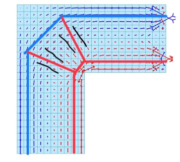 Fig 8 – Corner Joint STM where Negative Moment Zone
The figure above shows the stress distribution when the parent moment acts on the corner joint. If you design the STM according to the stress distribution, it is easy to locate the main reinforcing bars arranged along the tensile material outside the joint. In addition, it is possible to predict the compression material acting in the diagonal direction and the concrete cracks that may occur in the parallel direction, and to reinforce the U-stirrup in the vertical and horizontal directions in response.
Now let's take a look at the support part of the Reich Bridge. The model on the left below is designed with plastic theory, and the model on the right is designed based on the stress distribution during elasticity analysis.
We are well aware that the model on the left is not appropriate and that it will fail before the design strength. Because the actual behavior does not match the model used in the design. When a concentrated load acts on the end, it can be predicted that a tensile force acts on the area in the horizontal direction, which results in a vertical crack. Eventually, this crack develops and causes a fracture in which the corner part falls off before the design strength is expressed. The failure of the support for the Reich Bridge looks like this.
What about the model on the right? First, elasticity analysis allows horizontal tension to be considered in the design and correspondingly, horizontal reinforcement. This prevents vertical cracks from growing and helps the flow of force in the desired shape appear when the maximum strength is expressed. If we had designed the support part of a Reich bridge based on this model, we wouldn't have planned the area where the heavy load is applied to the plain concrete.
%20and%20elastic%20theory%20(b)%20when%20a%20concentrated%20load%20is%20applied%20to%20the%20edge.png?width=650&height=437&name=Comparison%20of%20the%20flow%20of%20force%20according%20to%20plastic%20theory%20(a)%20and%20elastic%20theory%20(b)%20when%20a%20concentrated%20load%20is%20applied%20to%20the%20edge.png) Fig 9 – Comparison of the flow of force according to plastic theory (a) and elastic theory (b) when a concentrated load is applied to the edge
Fig 9 – Comparison of the flow of force according to plastic theory (a) and elastic theory (b) when a concentrated load is applied to the edge
3. Result
The strut tie model is not only a useful tool to design the D-region of a concrete structure, but also a means to intuitively judge the flow of force within the structure. If you can express the flow of force in a visible way, you can also consider the shape of the right reinforcement for the design. Of course, it is not easy to find the right strut tie model for the situation. It is because there is not only one correct answer in a situation, but there can be many answers. The reliability of the model varies greatly depending on the understanding and experience of the structural designer. In particular, in some cases, cracks may occur that exceed the allowable value even under the load and, in some cases, there is a risk of collapse before the design strength. However, if you understand the above and experience many cases, I am confident that you will be able to design an appropriate model with sufficient reliability.
I hope the above will help you understand STM and broaden its practical application.
[References]
[1] Hans Reiffenstuhl. (1982). Collapse of the Viennese Reichsbrücke: causes and lessons
[2] Schlaich/Schärfer. (1998). Konstruieren im Stahlbetonbau, Betonkalender 1998 Teil. Ernst & Sohn
[3] Mattias Jennewein. (1989). Zum Bemessen des Stahlbetons mit Stabwerkmodellen
/%EA%B9%80%EC%84%B1%EC%9A%A9%20240_240.png)
I'm Kim Sung Yong, a structural engineer with a Diplom-Ingenieur from RWTH Aachen University and experience in research and teaching at TU Braunschweig's Institute of Reinforced Concrete. Currently working on various architectural and civil projects, I share my expertise through my YouTube channel and have contributed to major works like the KT Headquarter Est in Seoul and the Parkapartments am Belvedere in Vienna
※ Click on the keywords below 'Topics' to view related content.

/%EC%9E%91%EC%9D%80%EC%97%B0%EB%AA%BB_400_400.png)