The previous article discussed how to solve a dynamics problem by hand (OK by Excel). In this article, the basics of dynamics will be reviewed.
 Fig1 Simple Beam
Say we are calculating the center deflection. The load is P(t). P(t) means the load is not constant and varies with time, something like Fig2.
.png?width=463&height=257&name=Fig2%20P(t).png) Fig2 P(t)
Fig2 P(t)
However, in the meantime, we assume P(t) is constant as P.
Returning to Fig1, the span length is L, and flexural stiffness is EI. If we can recall what we learned from Mechanics of Materials, deflection at the span center would be

Is this correct?
This is correct only if the load P slowly applies from zero to the total value P. In other words, if P varies linearly between P(t=0)=0 and P(t=∞)=P, as shown in Fig3, the deflection at the center should be Δ static = PL3/(48EI).
=0%2c%20P(t=%E2%88%9E)=P.png?width=975&height=441&name=Fig3%20P(t=0)=0%2c%20P(t=%E2%88%9E)=P.png) Fig3 P(t=0)=0, P(t=∞)=P
Fig3 P(t=0)=0, P(t=∞)=P
We all know that this is not feasible in real-world engineering. What happens if the load P does not apply very (whatever this means) slowly?
The easiest way may be to check the extreme case as shown in Fig4, say P(t=0)=P, so-called suddenly applied load or impact load, etc.
 Fig4 P=const, Suddenly Applied Load or Impact Load
If the load P applies suddenly, i.e., P(t=0)=P, the deflection would be twice of Δ static, and this can be proved easily from Timoshenko’s Mechanics of Materials, 2.8 Impact Loading.
It may be logical if we have the following questions. What happens if the load P reaches its maximum value somewhere between zero and infinity? Twice of static value is too much. What is the minimum loading time, say if we can allow 5% of additional response, etc.?
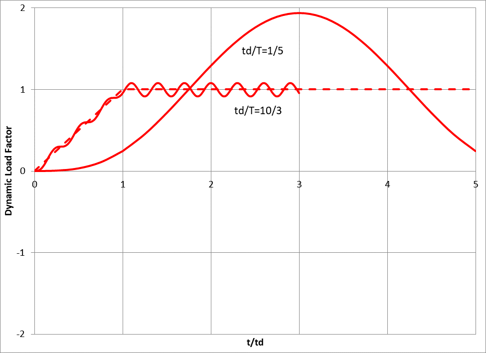
We can answer all these questions by dynamics. Before starting complex discussions, it may be helpful to review some genius work. A more general case can be found in Dr. Biggs, Introduction to Structural Dynamics, Fig 2.6D, as shown below.
 Fig5 Figure 2.6D from Dr. Biggs
The dashed line shows the loading diagram. At t=0, P=0, and at some arbitrary selected time t=td (t/td=1), P=P max. Then if the loading time td is very short compared to the natural period of structure T, say td/T=0.2, the maximum response (deflection is one of them) is around twice that from static (again if the load P applies very slowly). This is as expected from Timoshenko’s simple case.
Also, we can see that if load P applies very slowly, i.e., if load P reaches its full value at td=(3.333)T, the response is approximately proportional to the loading. This graph looks very simple and very easy to use. However not that simple to generate (Thanks to Dr. Biggs!).
Let’s review the previous example again. Let K = 48EI/L3 = 2000 lb/ft, total beam weight is W = 64.4 lb (assumed to be lumped at the span center, which is not correct), then the natural period is

Assume the loading is as shown in Fig2.
We can see that the load P starts half of P max and reaches its maximum value at around 0.5T, which is much shorter than 3.33T, but somewhat larger than 0.2T. (It is easy to regenerate Fig5 with td/T=1/2; however not shown here). So we can guess that the maximum response may be close to twice the static value.

Without further calculation, we can catch that the maximum deflection would be less than (2)(Δ static)=0.1 ft.
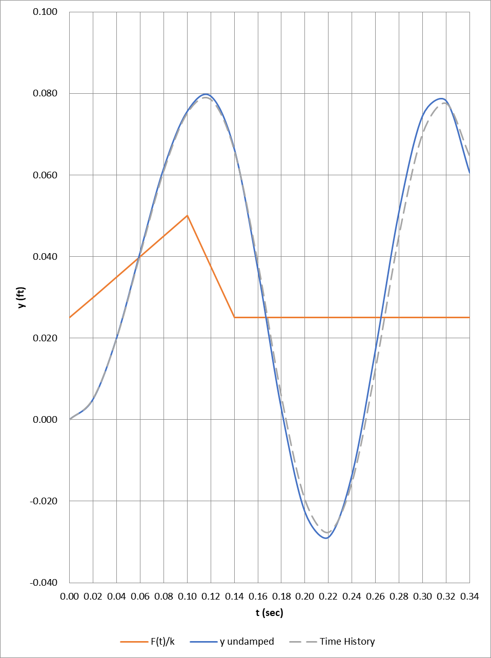
Now we can solve this problem by hand or by MIDAS. The results are shown in Fig6.
 Fig6 Time history analysis result
In Fig6, the red line shows static results, the blue line shows results from by-hand (Excel), and the green dashed line shows rigorous time-history analysis results from MIDAS. The maximum deflection is around 0.080 ft and less than (2)(Δ static), but somewhat close to it, as expected.
For dynamics, the loading itself is very approximated (how can we exactly estimate wind or earthquake?), and rigorous calculation to increase some percent of accuracy hardly makes sense. Old design charts like Fig5 are very easy to use and can minimize human mistakes. I highly recommend it, at least for preliminary design or for checking.
#Dynamics Problem Solving
#Deflection Analysis
#Impact Loading

He is a Senior Supervising Engineer with a high level of expertise in the design and analysis of suspension bridges. He has a solid fundamental understanding of structures and can apply his knowledge exceptionally well to the design and analysis of highly complex structures. He is also a strong communicator, able to identify and distill the key information that is relevant to the task at hand and present it in a clear and quickly understandable manner.


![Design and Practical Examples of Baseplates and Anchor Rods [sample download]](https://2495902.fs1.hubspotusercontent-na1.net/hubfs/2495902/%EC%8D%B8%EB%84%A4%EC%9D%BC22.png)
![Understanding Drafting Standards [ Drawing download ]](https://2495902.fs1.hubspotusercontent-na1.net/hubfs/2495902/%EC%8D%B8%EB%84%A4%EC%9D%BC24.png)
![Key Changes in ACI 318-19: A New Standard for Structural Design [ PDF download]](https://2495902.fs1.hubspotusercontent-na1.net/hubfs/2495902/%EC%8D%B8%EB%84%A4%EC%9D%BC21-1.png)
![Design and Practical Examples of Lug design(ASME BTH-1) [sample download]](https://2495902.fs1.hubspotusercontent-na1.net/hubfs/2495902/%EC%8D%B8%EB%84%A4%EC%9D%BC20-1.png)


