Intro
While many of my fellow engineers have dealt with general 2D analysis of tunnels, it seems that there is still a lack of proper resources on vertical shaft structural analysis. Therefore, I would like to share my limited knowledge on this topic.
What is a Vertical Shaft?
A vertical shaft can be thought of as a tunnel that is oriented vertically. Vertical shafts are planned and constructed for various purposes. Firstly, there are construction shafts. These are vertical shafts constructed along the planned route to shorten the excavation period and thus reduce the overall construction time. Besides this, vertical shafts are also installed for purposes such as emergency escape routes and ventilation. In Korea, vertical shafts are constructed in deep-level infrastructure projects (depths of 40 meters or more) for roads, railways, and other social overhead capital (SOC) projects.

In the case of vertical shafts, they are influenced by external air, so it is necessary to apply temperature differences between the inner and outer surfaces as well as seasonal temperature variations. Therefore, more loads and load combinations need to be used compared to the structural analysis of typical tunnels. The midas Civil program was used for the 2D analysis of the vertical shaft.
Vertical Shaft Analysis
1. Modeling
When performing an analysis, it is important to appropriately divide the size of the members to be modeled.
Particularly for vertical shafts, if the member sizes are modeled too large, it becomes difficult to accurately represent the circular shape of the members. Conversely, if the model is too detailed, it can cause inconvenience when working in midas Civil.
In my case, I recommend modeling the members with sizes between 0.4 meters and 0.6 meters.

2. Input Boundary Conditions
Attach springs to the modeled members to simulate the surrounding ground. Apply the ground spring coefficient using the validated theoretical formulas from the fields of tunneling and geotechnics (AFTES’s formula).
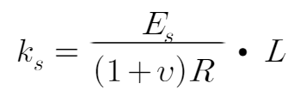 Formula for calculation of the coefficient of subgrade reaction
-
Ks:Ground spring coefficient
-
R:Radius of concrete lining
-
Es : Deformation modulus of the surrounding ground
-
v : Poisson's ratio of ground
-
L : Tangential length of the member
3. Calculation of Applied Loads
There are a total of 8 loads (self-weight, relaxed rock load, residual pressure, dry shrinkage load, seasonal temperature load + value, seasonal temperature load - value, internal and external surface temperature load + value, internal and external surface temperature load - value) acting on the vertical structure, and each load requires the application of load combinations.
(1) Self-weight
Self-weight refers to the load exerted by the structure's own weight, and it is calculated using the Self Weight function in midas Civil.
Navigate to [Load] > [Static loads] > [Self weight].
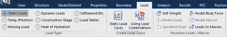 Fig. 2. Self-weight
(2) Relaxed rock load
The relaxed rock load acting on the structure refers to the weight exerted by the soil or rock as the ground undergoes relaxation. This load is equivalent to the unit weight of the soil or rock. Refer to the author's previous documentation for methods of calculating the relaxed rock load (Link: Lining Surcharge Load for Tunnel Structure Analysis).
When calculating the relaxed rock load, it's essential to identify a representative cross-section within the applied support pattern where the load is expected to be most significant. Unlike typical tunnels, vertical structures undergo continuous changes in ground conditions along the vertical direction, and the load values vary depending on the overlying soil. If you have determined the relaxed rock load using the Terzaghi rock classification table, the determination of the cross-sectional location is not important. However, if you used the GLI model or other calculation methods, you must select the representative cross-section within the support pattern where the overburden is deepest, i.e., where the relaxed rock load is greatest, due to the influence of the overburden, for analysis.
For the relaxed rock load, it is applied vertically downward on the structure. In my case, a surcharge load was applied in conjunction with the relaxed rock load.
Navigate to [Load] > [Beam load] > [Line or trapezoidal loads].
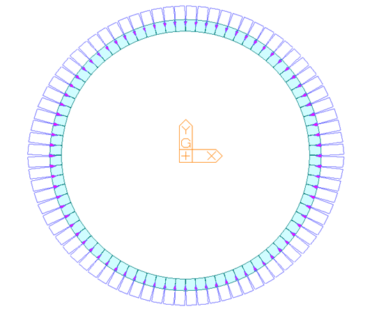 Fig. 3. Relaxed rock load
(3) Hydrostatic Pressure or Residual Pressure
Apply hydrostatic pressure acting on the structure. If residual pressure acts on the structure, depending on the ground conditions, apply either one-third or one-half of the residual pressure. If hydrostatic pressure acts on the structure, select the analysis section and apply the pressure of that section.
Navigate to [Load] > [Static Loads] > [Beam load] > [Line or trapezoidal loads].
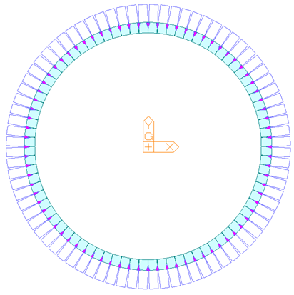 Fig. 4. Residual Pressure
(4) Seasonal Temperature Load and Dry Shrinkage
Due to Korea's distinct four seasons, it is necessary to apply seasonal temperature loads and dry shrinkage loads to sections affected by external conditions. This input accounts for the temperature load exerted on the structure. Utilize the System Temperature Load function to apply temperature loads. I applied temperature loads of +15°C and -15°C for seasonal variations, and -15°C for dry shrinkage. In regions with extremely low temperatures such as Cheorwon, it's important to consider the region's characteristics. For regions with consistently high or low temperatures, it's recommended to set the initial temperature in the structure type and perform the analysis accordingly. (In polar regions, set the initial temperature to a low average temperature, while in desert regions, set it to a high average temperature.)
Navigate to [Load] > [Temp/.Prestress] > [System Temp.].
 Fig. 5. Seasonal Temperature Load and Dry Shrinkage
(5) Internal and External Surface Temperature Load
The structure of a tunnel is in contact with the ground, thus influenced by the ground conditions. Particularly, temperature variations occur between areas in contact with the ground and those that are not. These temperature differences need to be accounted for as temperature loads. Additionally, temperature variations occur in areas exposed to external conditions. I applied temperature loads of +5°C and -5°C.
Navigate to [Load] > [Temp/.Prestress] > [Temp.Gradient].
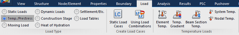 Fig. 6. Internal and External Surface Temperature Load
(6) Input Load Combination
Just input the load combination according to the load combination provided in the Structural Concrete Analysis and Design Principles. Below is an example of load combination selection based on Korean design standards.
.png?width=1698&height=1166&name=Fig.%207.%20Load%20Combinations%2c%20Structural%20Concrete%20Analysis%20and%20Design%20Principles%20(KDS%2014%2020%2010).png) Fig. 7. Load Combinations, Structural Concrete Analysis and Design Principles (KDS 14 20 10)
Fig. 7. Load Combinations, Structural Concrete Analysis and Design Principles (KDS 14 20 10)
4. Calculation of Reinforcement Quantity after Analysis
Select the load combination with the highest structural demand from the load combinations. Summarize the analysis results and calculate the structural demand. Then, design the reinforcement quantity based on this demand.
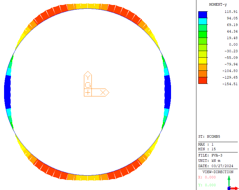 Fig. 8. Analysis Results
Comparison of Results between 2D and 3D Structural Analyses
The results of analysis differ between 2D vertical shaft analysis and 3D vertical shaft analysis. Let's examine the comparison data of structural demands in 3D structural analysis.
| 3D Vertical Shaft Moment | 2D Vertical Shaft Moment |

|

|
The reason for the difference in structural demands is typically because as the vertical shaft descends, the ground conditions generally improve. Thus, it's common for the support pattern below to be better. However, even with a better pattern, it doesn't necessarily mean the structural demands will always be lower. The first reason is that the concrete self-weight of a massive structure like a vertical structure acts entirely in the vertical direction. The second reason is that at the bottom, most vertical structures develop connection transverse joints, leading to the formation of joint connections, which can result in greater structural demands. Therefore, it's emphasized not to rely solely on the results of 2D analysis for reinforcement detailing and to perform 3D analysis.
Additionally, it's impossible to consider the self-weight of concrete in 2D vertical structure analysis, and to perform vertical structure analysis accurately, 3D structural analysis must be conducted. It's advised not to conclude the analysis solely based on 2D analysis but to perform additional 3D analysis and compare the results for the engineer's judgment and design decisions.
Conclusion
This post is based on functional aspects to provide advice, targeting those who have a basic understanding of performing structural analysis for typical tunnels, assuming they are capable of conducting basic 2D structural analysis for tunnels. We explored how to represent the influence of temperature in 2D structural analysis of vertical shafts and investigate which functionalities of midas Civil are utilized.
For any aspects not covered in this explanation, I have attached the analysis file for download. Please open it directly to obtain the information. (👉 Click to download 2D Vertical Shaft Structural Analysis Model File.)
References
Structural Concrete Analysis and Design Principles (KDS 14 20 10, Korean Design Standard)
Detailed Design Criteria for Concrete Lining (Korea Expressway Corporation, 2016)
#Vertical shaft analysis
#Temperature loads
#2D vs. 3D structural analysis
/Steve%20Choi_346_240.png)
I'm Steve Choi, a tunnel structure engineer with a background from Seoul National University of Science and Technology, experienced in both specialized tunnel design and comprehensive engineering. Passionate about civil engineering, I seek collaborative innovation in tunnel and structural design within this community.
Experience:
- Researcher at the Construction Environment Research Institute, Seoul National University
-Worked as a Tunnel Design Specialist
-Worked at a Comprehensive Design Firm
※ Click on the keywords below 'Topics' to view related content.

![Design and Practical Examples of Baseplates and Anchor Rods [sample download]](https://2495902.fs1.hubspotusercontent-na1.net/hubfs/2495902/%EC%8D%B8%EB%84%A4%EC%9D%BC22.png)
![Understanding Drafting Standards [ Drawing download ]](https://2495902.fs1.hubspotusercontent-na1.net/hubfs/2495902/%EC%8D%B8%EB%84%A4%EC%9D%BC24.png)
![Key Changes in ACI 318-19: A New Standard for Structural Design [ PDF download]](https://2495902.fs1.hubspotusercontent-na1.net/hubfs/2495902/%EC%8D%B8%EB%84%A4%EC%9D%BC21-1.png)
![Design and Practical Examples of Lug design(ASME BTH-1) [sample download]](https://2495902.fs1.hubspotusercontent-na1.net/hubfs/2495902/%EC%8D%B8%EB%84%A4%EC%9D%BC20-1.png)